Day One
So, after wrapping up a few other projects, I've finally gotten the opportunity to begin construction. I think that I have most of the design completed in my head, but haven't really sketched anything out, sorry. I'll try and be descriptive with the pics so everyone can get the "drift"..
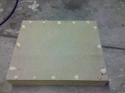
Step One: Build a base.
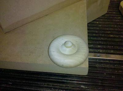
Everything needs to be fixed in relation of the platen surface (the glass that will compress the pages). This being of utmost importance, there will be beams to mount lights, the platen, and the cameras extending up from the sides. I've decided to use 1/2" MDF (Medium Density Fiberboard) that I have lying around as the surface. This material is commonly used for counters, cabinets, speaker enclosures, etc.. The frame of the base is made of "Select" grade 2x4's from Menards. Everything was screwed together with drywall screws (my favorite kind of screw). The screws are countersunk and the ones on the top have been filled with wood putty for no other reason other than cosmetics. You can see where I've marked the preliminary guides for the columns that will protrude upwards to support the cameras, the platen assembly, and the lights.
Base
Base2
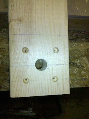
Light and Platen column Mounting
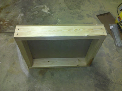
Base with rear column installed
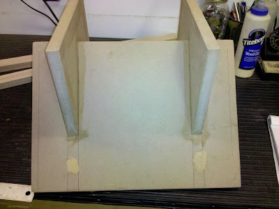
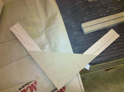
Step Two: Build a Cradle.
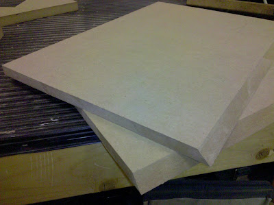
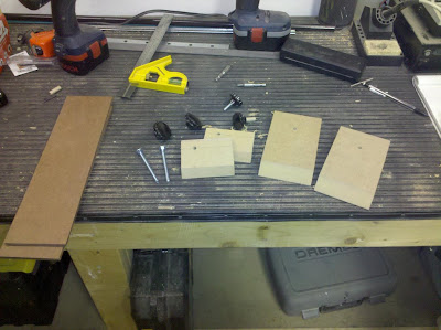
The book will need a place to rest during scanning. It needs to be parallel with the surface of the base, holding the book open at a 90 deg. Angle. Also desired is a "spine relief" achieved by adding thickness to the surface but leaving out a channel in the center of the cradle where the spine of the book will rest. I've decided to use some more MDF that I have. This time we're going to mix it up with some 3/4 MDF for the base support. I just feel that the bottom pieces that will support the "\/" should be more "meaty". I cut two \/ shaped base pieces and two 11" x 15" sides to start with.
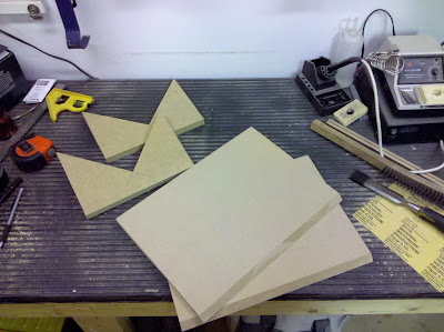
Cradle Pieces
3/4"x?x? Base
1/2"x11"x15" Sides
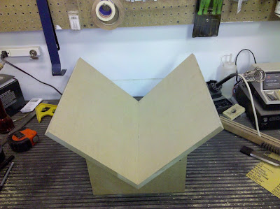
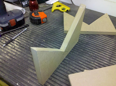
Mocked Cradle
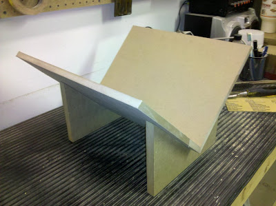
Mocked Cradle 2
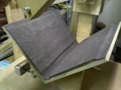
I cut the center pieces of the cradle sides at a 45 deg. angle for fit into the \/ in the base. Then I decided to incorporate some "spine relief" with some 1/4 inch hardboard (Really thick, dense cardboard). This material is commonly used in automotive applications in door panels, trunk floors, etc. I cut the hardboard the same length (15") as the sides. but about 3 inches slimmer (8"). Then I glued everything together with wood glue and weighed it down to dry. After they were dry, the base was pre-drilled, glued, and screwed together. The screw holes were filled with wood putty. Once dry, everything will be sanded and painted black. The top surface of the cradle will also get a grippy stuff treatment.
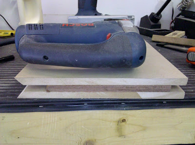
Spine Relief Drying
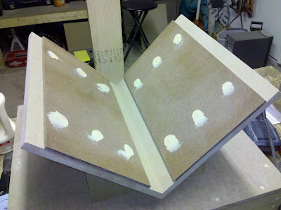
Cradle Assembled
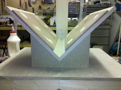
Cradle Assembled2
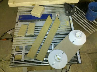
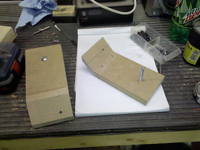
Step Three: Make a cool shuttle thingy.
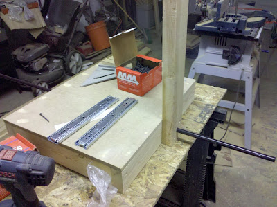
So, after some intense research on how to make the platen go up and down, I've decided to merge several ideas that I've found on DIYbookscanner.org. My idea is to create a "shuttle" that rides up and down the 2x4 vertical column at the rear of the base on a set of ball bearing sliders. The platen can then be attached to this shuttle in a fixed or adjustable manner. Built in this fashion, I feel that the smoothest operation can be attained whilst keeping the platen as perpindicular to the cradle as possible (for better scans). The shuttle will be constructed of 3/4" MDF for strength.
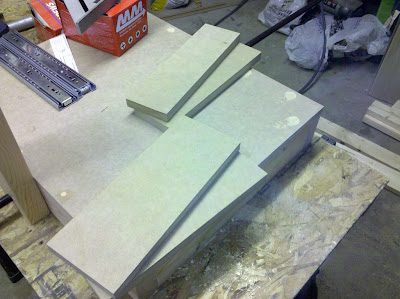
Shuttle Pieces
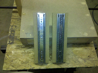
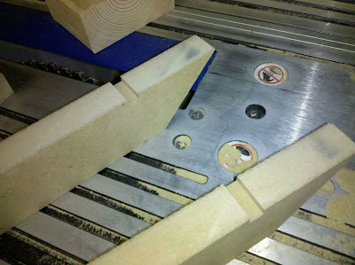
Ball -bearing sliders mounted on the sides pieces of the shuttle.
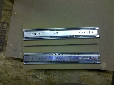
Ball -bearing sliders mounted on the sides pieces of the shuttle2.
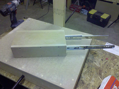
Shuttle assembled with ball-bearing sliders extended.
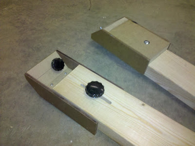
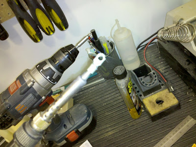
Step Four: Ponder what it would be like lifting the platen 300 times.....
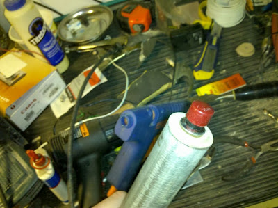
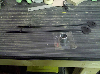
After building the shuttle, I realised that the shuttle/platen assembly would be pretty heavy and cumbersome. I have planned from the start to put some sort of counterweight or spring assist to help with the repetitive vertical operation of the platen assembly. After thinking about it for a while, I've decided that this won't be sufficient for comfortable operation of the machine. The new plan is to make the lifting of the platen lever-operated. A combination of a shaft, lever, arm, and spring will be required to make this happen. The base also requires slight modification. Considering that I have most of the materials to do this lying around my garage and a welder for the more delicate metalwork involved, what the hell. Sean's arm will thank me.
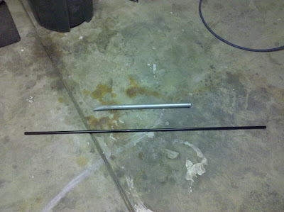
Pipes 'n Stuff
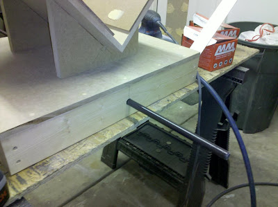
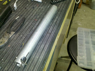
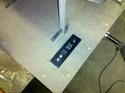
Shaft in base front
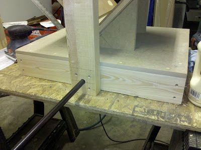
Shaft in base rear
Day Two
So the main goal today was to get the glass and other misc. materials together for the construction of the platen assembly. I got two 11"x15" pieces of glass from ACE (they're AWESOME) and some small threaded steel rod to solve the glass touching at the bottom delimma and adding some rigidity at the same time. Once I got home, I realised that I made the original pieces of the base with 11"x15" stock. The platen won't clear the sides of the book cradle if I don't do something.
Step Five: Trim 1/2" off of the top and bottom sides of the cradle (in relation to a book placed inside).
I cannot stress how difficult it was to trim the cradle with it glued and screwed together, it's damn near finished. Hopefully this will be it for the mistakes; I doubt if we're going to be able to use something that's only big enough to scan paperbacks..
Time to do some trimmin'
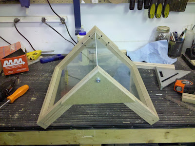
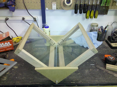
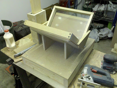
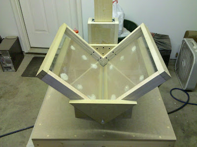
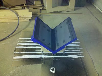
Step Six: Build the Platen Assembly.
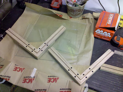
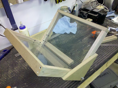
Ok. With the backstepping out of the way, time to build a platen. I decided to use 3/4" MDF and some 3/4"x1/12" Oak hardwood to build the platen with. I used my tablesaw to cut notches 1/8" wide by 3/8" deep for the glass to notch into before cutting any angles on all pieces; this will ensure a tight fit and less stress on the glass. I used a miter saw to cut all of the angles. All joints were glued and screwed as usual, unless the pieces may require disassembly. The threaded rod provides approximately 1/16" of gap between the glass pieces on the inside of the \/. It also connects the bottom of the two sides adding a lot of stability. Once assembled, the platen assembly feels nice and solid. Miraculously, everything actually even wound up true. Thumbscrews were placed onto the ends of the threaded rod to secure it in place and tighten up the bottom of the frame.
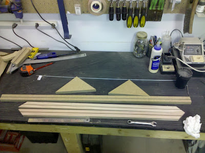
Platen materials
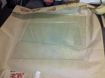
Glass
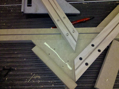
One side of the platen
Both Platen sides completed.
Platen side, outside view
Platen assembly.
Threaded rod
Platen assembled bottom
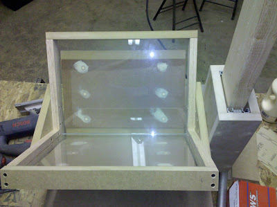
platen assembled front
platen assembled profile
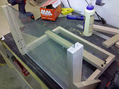
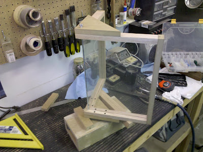
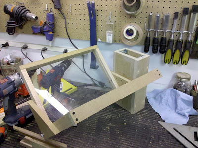
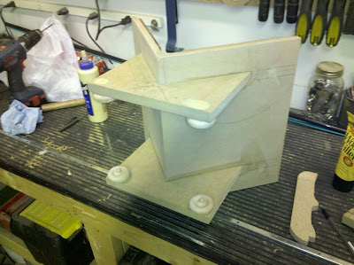
Step Seven: Add the shuttle to the platen.
The platen was attached to the shuttle with four drywall screws. This joint wasn't glued, just in case some shimming or "suspension" is required to keep everything straight while scanning. After I was done building, I decided to kind of stack it all together. I'll be damned but this thing is actually starting to look like something.
Platen/Shuttle mockup
Platen Assembly rough finished
mockup 3/4
mockup front
mockup side (thank god the glass is dirty).
Day Two-and-a-third
So today's challenge starts with the sliding mechanism(s) for the cradle. My first attempt was a bit old fashioned, very cheap, and failed miserably.
Wooden Wheels
Wooden Wheel Close-Up
So, after realising that these arent' gonna be smooth enough, no matter how much veggie oil that I apply to the pegs, they were chiseled off, sanded smooth, and holes filled in preperation for the next attempt.
Day Three
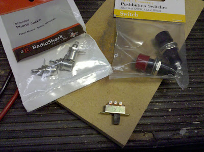
This part of the project has been killing me. I needed something to make sure that the cradle can slide left-right but refuse to spend a lot of money or resources, so I went shopping..
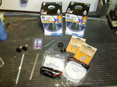
Yaay, parts!
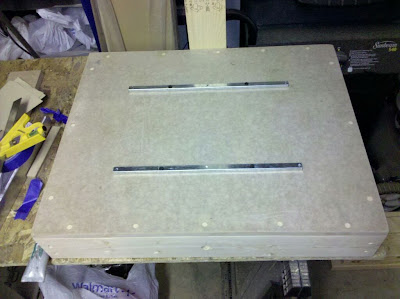
With some cheap nylon wheels designed for a screen door and a plethora of other miscellaneous parts, construction begins again. I had to build little "arms" for the wheels to mount to the cradle and lift it up a bit. My original idea for the "rails" mounted to the base for the wheels to follow was also implemented. The metal parts were from a garage door install kit and a floor transition mounting kit. No, I don't throw much away. The metal pieces were trimmed and massaged into shape with an angle grinder and a drill. Wheels were mounted to their metal bracket and attached to the cradle.
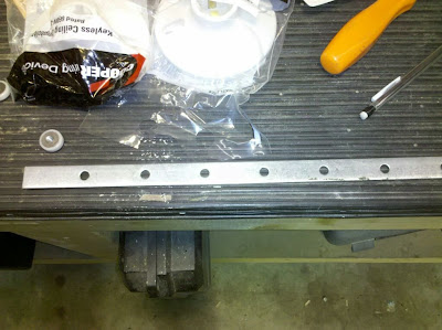
Garage door opener hanger strip (cheap, didn't use it)
Channels from mounting hardware for floor transition (extra)
Wheels mounted on cradle
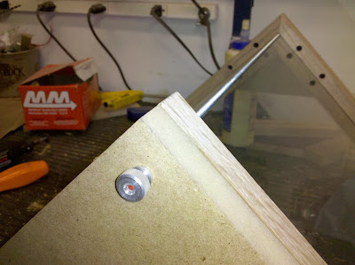
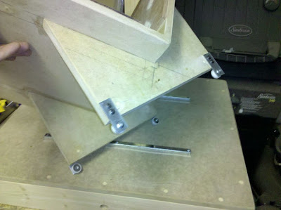
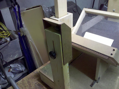
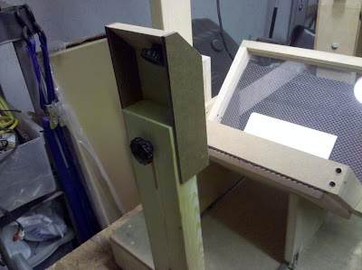
Before the guides could be actually screwed down to the base, the exact location of the base needed to be determined. I've been dreading attaching the shuttle to the center pillar, those damn ball-bearing sliders are so hard to mount. The mounting went smoothly and I went ahead and installed the spring after using another piece of that garage door opener strapping to fashion a "hook" for it to connect to the shuttle. The top spring mount is a screw for now, things may need adjustment. Also, I had to put a shim in between the platen and shuttle assembly at the bottom to maintain perpindicularity (webster, eat your heart out). Loving how it's turning out so far.
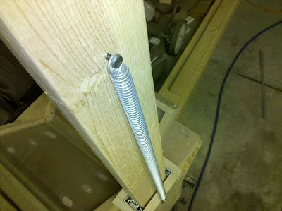
Spring
Back View
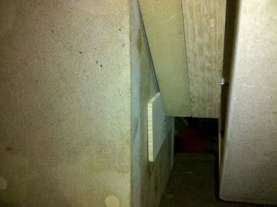
Shim
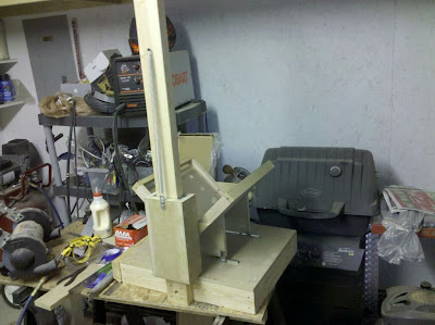
Front View
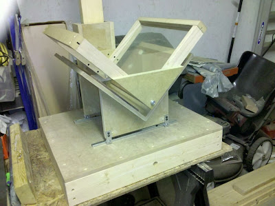
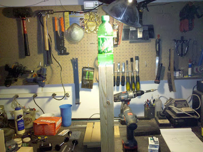
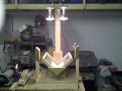
After much measuring, aligning, and admiring how smoothly the platen travels up and down it's tracks, and how nicely the cradle self-centers itself; I decided that I need to shed some additional light on the subject. All pieces were glued and screwed as this shouldn't be disassembled. There were three things that I decided that were important to the construction of this piece.
1. It must be moveable (at least for now)
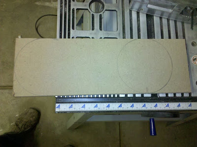
2. The lights should be 8 inches apart on center. This will place them directly centered over each platen.
3. The lights need to extend out from the arm to be centered over the platen as well, not right against it.
When I grow up, I'm gonna be a light fixture.
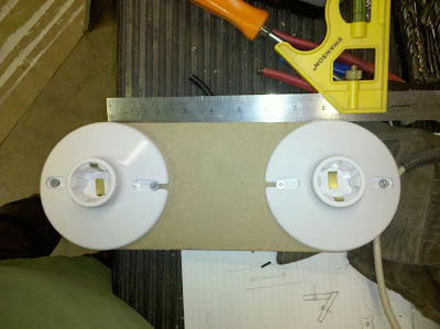
Sockets Mounted
Sockets wired.
All of the pieces prepped.
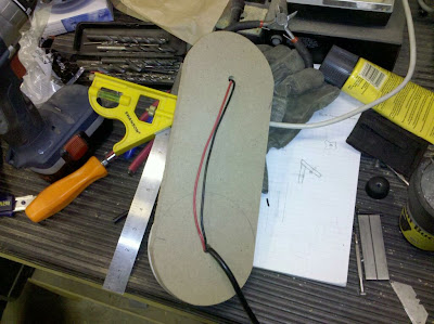
Those wires gotta go somewhere
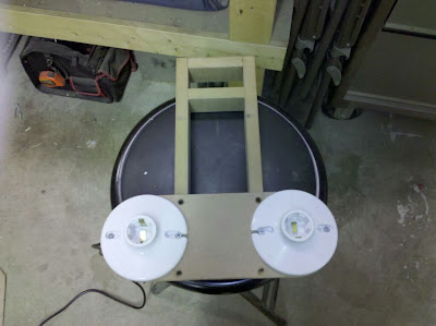
Light Assy. bottom view assembled
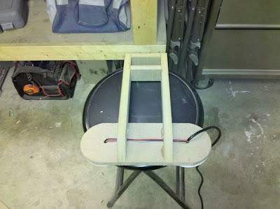
Light Assy. top view assembled
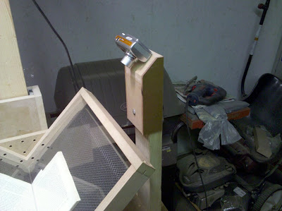
With all of this completed. I wanted to try it out a bit. So I lit it up and took a few pics with my Android (which has been the camera for the entire project so far, btw). Looking great so far!
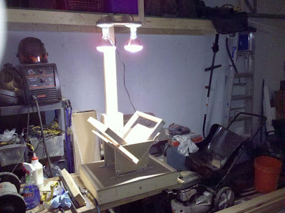
Where we are so far.
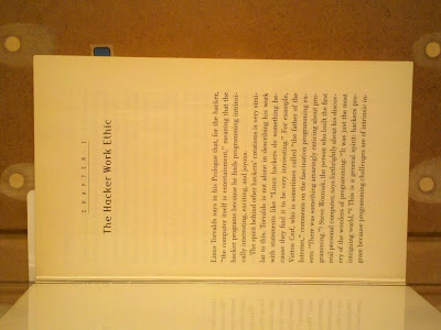
Pic Taken with Flash
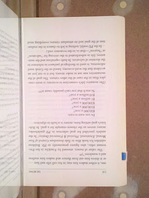
Pic Taken with scanner lighting
Day Four
Now that the main components are lined up and operating smoothly. Time to add some camera mounts. My goal was to make them solid, adjustable, and long lasting. Pillars were made from 2x4's and the sliding camera mount platform is made of a combination of 3/4" and 1/2" MDF, and 1/4" Hardboard. The channel for the lock bolt was routed with a 1/4"x1 1/2" plunge bit.
Camera Mount parts
Front pieces with carriage bolts installed.
Completed Camera Mounts
what i call artistic photography
My cousin painted the surface of the cradle; then we went ahead and put the grippy stuff on. This stuff works really well! The grippy stuff was attached with spray adhesive liberally applied to the painted surface of the cradle, then trimmed with a utility knife.
Painted Black
Grippified
Finally, it's time to mount the camera mounts. This was done in the same fashion as the rear pillar, making sure that the board was perfectly plumb. The height of the mounts and the range of adjustment was determined first by finding where the lowest point that the camera would need to be positioned, the adding however many inches you think that the machine can handle (that's what she said). The end solution was more than adequate. Would've included some scans from the Canon, but I'm a chump with no SD cardage.
Mount Lo
Mount Hi
Mount w/Cam
Mount w/Cam closeup
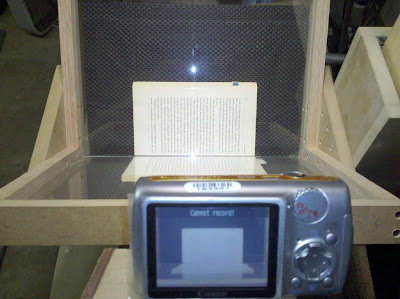
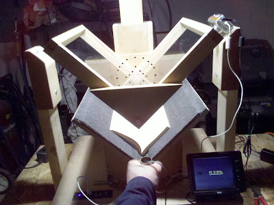
Sweet lord she frames up nicely.
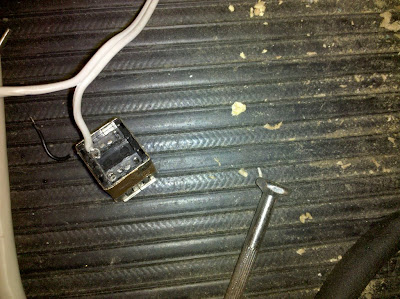
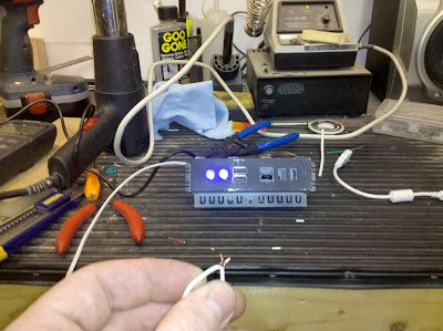
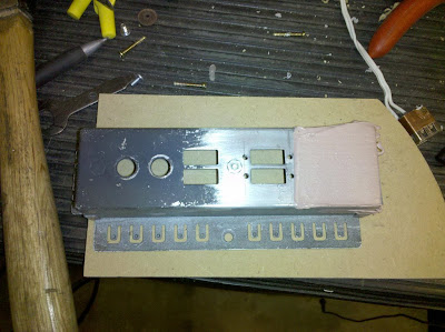
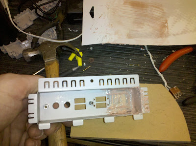
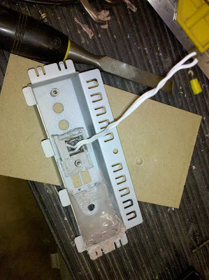
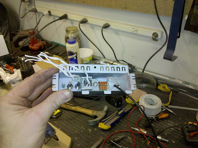
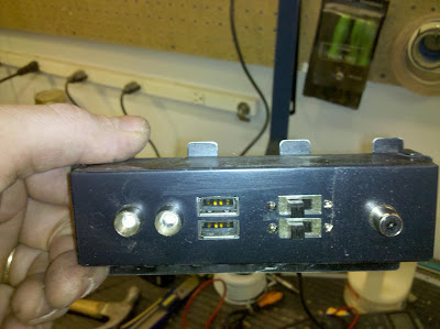
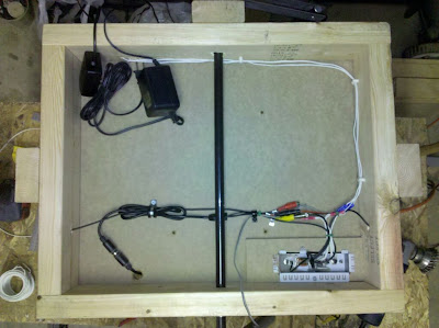
With all of these things finally falling into place, I had to face the inevitable challenge of wiring it all up. To my surprise, I didn't have half of the switch and connector parts laying around that I thought I did. I made an awesome find while looking for some usb ports for the cameras and scored a whole base for a control panel w/ USB connectors. I threw in some blue 5v led's for some feedback. The left LED on the panel is to indicate that there is power to the panel. The right one illuminates when the switch contact is closed and there is power at the USB ports. What to do with all of those empty sockets?
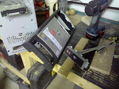
SCORE!
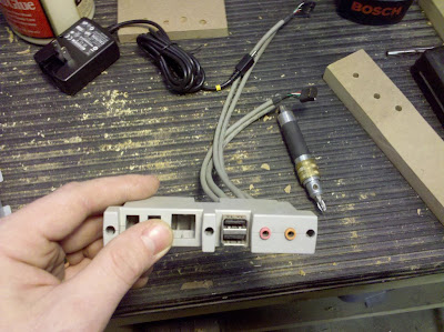
USB panel guts
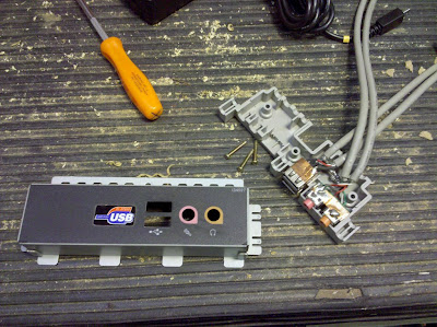
Deeper into the guts
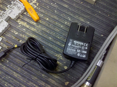
Bonus: old motorola phone charger, 5v
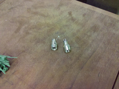
Fancy blue leds w/wide angle blingtastic reflector mounts
my bitch
USB ports wiring
Control Panel beta
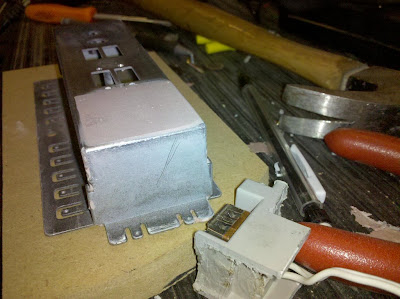
Day Five
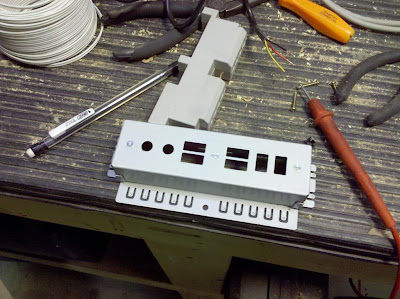
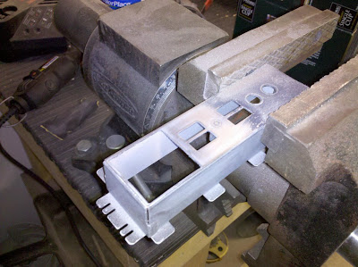
Whew, things are really coming along and excitement is building. Decided to scrap a LOT of the original control panel. It wasn't pretty.
Materials involved:
- Original USB panel parts
- Scrap Aluminum
- 1 Minute Fast-Dry Epoxy
- Hot Glue
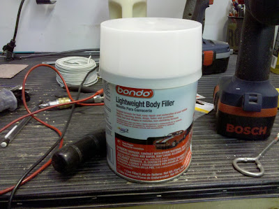
- Bondo
- Panel Mount RCA Jack
- (2) SPDT Slide Switches
- (2) LED Indicators
- (2) USB Ports
out with the old
Replacement metal
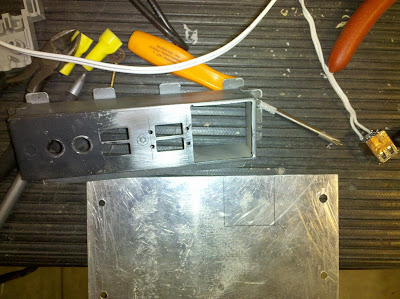
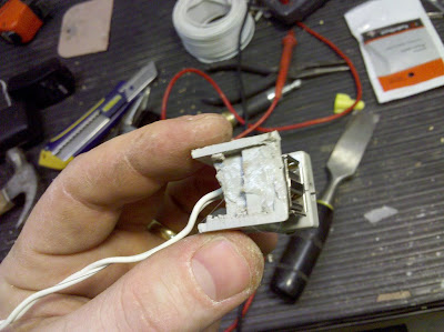
Bodywork
Bodywork_Inside
kinda like spam, but different
Trimmed down to USB only
DIY Plastic Welder
Switches and buttons and plugs, oh my
Ready for paint
insert USB
LED's, USB, and Switches mounted
Control Panel
Instead of putting 3 RCA jacks on the panel to connect the cameras and external video display all together on the panel, I decided to make some little connector plate thingies to make things smoother. Wires were soldered to these and they were installed on the base of the machine near each camera mount. This will reduce the cable clutter a bit.
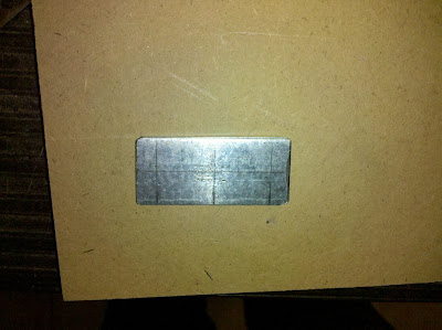
Marked and ready for drilling
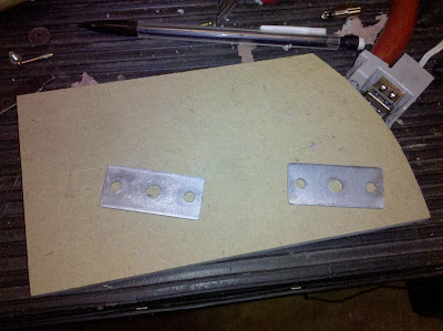
Holes drilled
Ready for mounting
Day Six
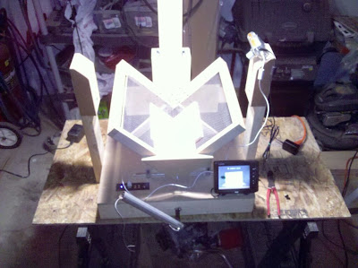
Now that the electronics and mechanics are pretty much complete. Now is the fun part of mounting and connecting everything. Also, I needed to fabricate the lever assembly that will raise and lower the platen. I also found an old 5 1/4" LCD screen that has a minor blemish in it while I was sorting through my parts looking for other stuff. I've decided to add it to the project as it's good enough to aim the cameras.
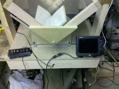
Monitor and interface panel mock-up
Shutter switch fab
shutter switch fab_2
Shutter switch/handle mock-up
Handle after machining
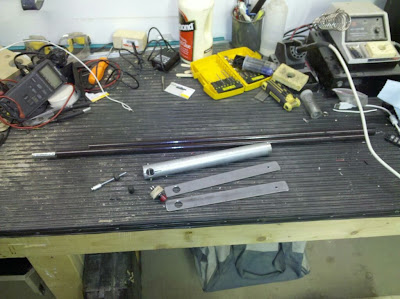
handle parts ready to assemble
install switch in handle
interface panel mounted
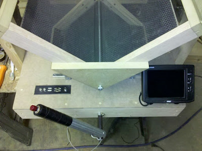
Panel, lever, and monitor installed
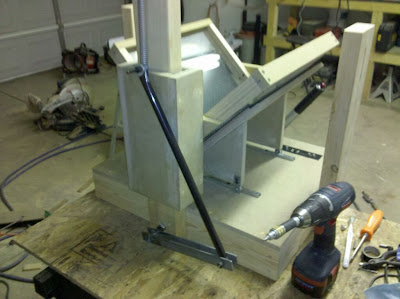
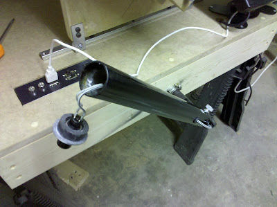
Rear lever assembly
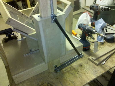
Rear lever assembly2
Finale
With all of the hardware and wiring installed, it's time to connect all of the wiring and tighten up all of the bugs. All in all, the machine turned out quite satisfactory.
Wiring on bottom of Base
Near Complete
Near Complete 2
Disaster Strikes
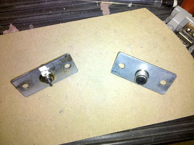
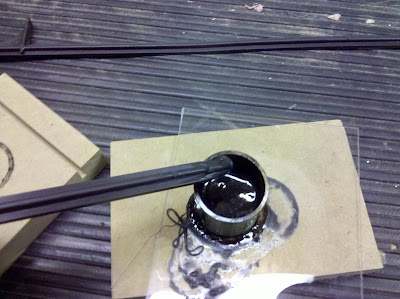
So, with the final component ready to install (the switch in the end of the lever), I set out to complete the machine. Next was some paint, a few needed welds on the handle, some sort of grip, and the shutter switch. I painted the handle black and added some grippy stuff for a grip.
The grippy stuff can be cut and sewn on kind of like the old-school leather (wrappers) for steering wheels. If you don't know what I'm talking about, you're probably in your mid-to-early 20's. This worked out GREAT, but I doubt that it'll stand the test of time like the rest of the machine. Which brings me to the switch.
The material that I used to "turn" the removable switch mount that fits into the end of the handle was MDF. Problem is, I had to remove so much material, that when I tried to put the screws in to hold the button assembly into the handle, the wood split out like crazy. I wound up with a few wooden washers with a switch mounted in one. This was frustrating, the switch needed to be removable because it WILL FAIL eventually. Mechanical things just break over time and this is the most likely failed part of the machine at this time. The solution was fun, something that I never tried before, and probably hazardous to my health...
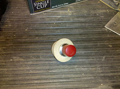
Some ABS (Plastic) sign stakes left by the lawn company
I love to melt stuff..
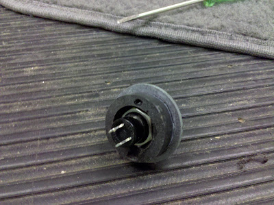
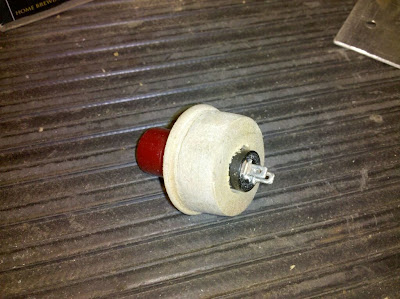
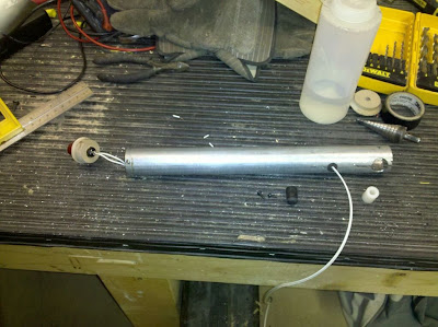
New shutter switch assembly 1
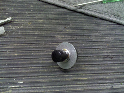
New shutter switch assembly 2
Almost there now..
So, basically, I just used a piece of the original stock for the lever as a mold, sprayed on some PAM (to keep it from sticking inside the mold), and melted the stakes into the mold with a heat gun. Once I had a nice thick little plastic "puck", it was machined to hold the switch. I epoxied a washer on the end so the repetitive pushing of the shutter switch wouldn't stress the tiny little screws that hold the switch assembly into the handle. You can't see it in the pics, but there are two holes drilled into the end of the handle so screws can be ran into the edges of the switch assembly, holding it in place. The end result was perfect, I doubt that the switch will ever fall out, but can be easily removed and replaced with another radio-shackish counterpart if it ever fails.
Well, that's it. I'm out of pictures for now. The completed machine includes nothing more than the other camera. Nothing else was painted as glare didn't turn out to be an issue.
FYI: The lever action is pretty simple. The lever always rests parallel with one of the sides of the platen (45 degree angle), so it's always out of the way (unless you're operating it). Per the photos, when you turn the lever to the right all of the way, the machine "locks" in the open position with the platen about 6-8 inches from the top of the cradle. To facilitate this, there's a rubber stopper mounted to the shuttle assembly just past center on the back of the machine that kind of gives you a "lock" as the connecting shaft rests against it. I wish I had photographed this simple little detail because it makes loading and aligning the book easier.
I will speak with the current owner about getting some more pictures and maybe some video for you guys.

