One more 80/20 build

Built a scanner? Started to build a scanner? Record your progress here. Doesn't need to be a whole scanner - triggers and other parts are fine. Commercial scanners are fine too.

Moderator: peterZ

Post Reply
ldolse
Posts: 12
Joined: 04 Mar 2014, 00:53

One more 80/20 build

Post by ldolse »

Hi, just joined the forums, but have been lurking for quite a while. I've been wanting to build a scanner ever since I came across Daniel's instructable, and this holiday season I'm using the time back home to do it. I live in Asia, where English books are expensive, and outside of popular titles a bit hard to come buy. I also travel a lot, so digital is my main preference for reading these days.

After going through all the different builds in the forum I fell in love with Translucent1's and Railman's 80/20 designs. That, combined with the fact that a friend of mine works at Grainger with a 40% holiday discount sort of clinched it for me.

P1030322.JPG
P1030322.JPG (427.25 KiB) Viewed 18763 times
I've more or less followed Railman's specific design - the CAD details were great, thanks BTW!! I made a few modifications here and there, and I took lots of pics, as I wasn't really sure how the 80/20 stuff worked after seeing photos of the other builds, and I thought that might be the case for others not familiar with it as well. It's definitely great stuff to work with, very much like an erector set.


The build is currently in progress, hence the unfinished pic - I'm waiting for paint to dry on my cradle, so figured it was a good time to post. Will add detail pics in later posts.
Detail
Detail
P1030326.JPG (184.16 KiB) Viewed 18763 times
Last edited by Anonymous on 25 Dec 2010, 00:31, edited 8 times in total.
ldolse
Posts: 12
Joined: 04 Mar 2014, 00:53

80/20 Basics & Frame

Post by ldolse »

There are many kinds/classes of 80/20 parts. First decision is metric vs. fractional. Railman's design uses two different types of fractional extrusions:
1"x1" 80/20 - the part number is 1010 - This is used for the Platen and cradle rails
2"x1" 80/20 - the part number is 1020 - This is used for the frame

The classification of these two extrusions is 10S - you just need to make sure the other 80/20 parts you purchase are 10S compatible if you choose these same ones.

Use carbide blades for cutting - this was mentioned in one of the other threads, but it's worth mentioning again. We started with a chop-saw, but it was impossible to get a clean/accurate cut. It's also a good idea to set up a stop for every piece you cut to make sure the other lengths of the same size are identical.

80/20 attaches together using two options - the somewhat cheaper but less adjustable option is to thread one side with a tap, and then drill a hole through the other piece to access the head of your bolt. The more expensive option uses an anchoring system and doesn't require any pieces to be drilled/tapped.

All the screws are 1/4 inch with the coarser thread, and you'll need that type of tap as well. I made a trip to the local hardware store which sells surplus and over-runs to pick up a bunch of other 1/4 bolts, washers etc which have come in handy for mounting other parts to the 80/20 frame. $1.50/pound for any non-80/20 hardware used throughout the build.

Thread tapping
Thread tapping
P1030294.JPG (185.8 KiB) Viewed 18799 times
Thread cutting oil makes a big difference, as does a sharp tap.


Drilling Access Holes
IMG_0014.JPG (141.73 KiB) Viewed 18799 times
Drilling the Access holes in the opposite pieces. Did one first, and then used the first as the template for the second. Getting the access holes in the right places is pretty critical to making sure everything can be squared/tightened easily. We generally used 1/4 inch access holes, but if you need some more wiggle room it shouldn't be a big deal to jump up to 5/16.


Connecting Right Angles
IMG_0012.JPG (103.82 KiB) Viewed 18799 times
The screws going in with the attaching nut. These need to be screwed down a bit more - so that it can slide into the channel - then final tightening happens through the access hole in the upper piece.


Attachment Nuts
Attachment Nuts
P1030286.JPG (95.92 KiB) Viewed 18799 times
Other pieces are generally attached using special nuts which slide into the channel.
Gusset for the verticals
P1030278.JPG (137.6 KiB) Viewed 18799 times
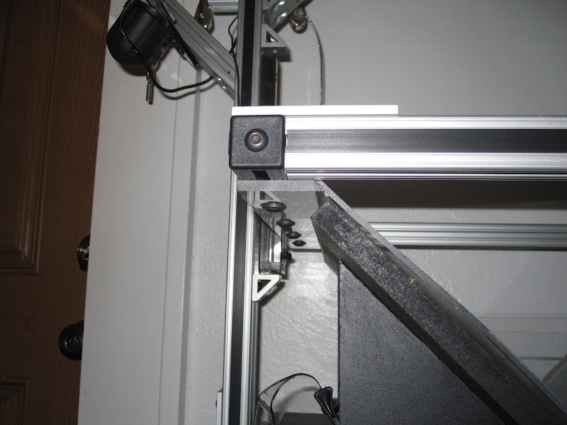
1020 Frame
1020 Frame
P1030277.JPG (243.63 KiB) Viewed 18799 times
This is the basic frame, all 1020 pieces. Five 20 inch pieces, 2 16 inch pieces. The 45 degree pieces are in the wrong place in this pic, and will be used for the camera mounts.
Last edited by Anonymous on 25 Dec 2010, 00:30, edited 4 times in total.
ldolse
Posts: 12
Joined: 04 Mar 2014, 00:53

The Cradle

Post by ldolse »

The cradle is one area where I veered from the other designs. The dimensions are the same as the other build (aside from using 3/4 inch plywood), but I wanted to take advantage of the sliding action that the new standard scanner uses to handle different sized book bindings, and I wanted to use something like the skate bearings that Daniel used in his most recent builds for back and forth travel.


Added 1010 rails for sliding
P1030287.JPG (117.67 KiB) Viewed 18795 times
The 1010 rails sit in the lower part of the base, the plywood cradle base will rest on top of that.

Patio door rollers
Patio door rollers
P1030308.JPG (96.43 KiB) Viewed 18795 times
Inline skate bearings didn't work well with the 1010 extrusions - the wall of the bearing touched the side of the rail, so it didn't roll. I found theses rollers at home depot, ~$7 a pair, and they worked perfectly. The included bolt was already the right depth and thread.

Scrap 1010 to facilitate adjusting for different book bindings
P1030302.JPG (97.1 KiB) Viewed 18795 times
Used a dado blade to cut a one inch groove for the 1010
P1030303.JPG (80.02 KiB) Viewed 18795 times
I used the dado blade to provide a little more room for larger bindings as well as facilitating accuracy while building the rest of the cradle. It's probably only an 1/8 inch or 3/16 in depth - more than that would make locking the cradle uprights to the 1010 difficult. Used four 3/4 inch carriage bolts to mount these, and I had to countersink them slightly so the base would still slide nicely. Flat-headed bolts would have been better, but the surplus hardware store didn't have them in 3/4 inch.
Attachments
Finished Cradle - Angle 2
P1030337.JPG (92.53 KiB) Viewed 18761 times
Finished Cradle - Angle 1
P1030336.JPG (110.24 KiB) Viewed 18761 times
Last edited by Anonymous on 23 Dec 2010, 03:42, edited 1 time in total.
ldolse
Posts: 12
Joined: 04 Mar 2014, 00:53

The Platen

Post by ldolse »

While Railman's CNC router bearings look like they rock, the best price I found on ebay was $99 for the same thing. I also looked at 80/20's linear bearings - ordered these just to check them out, and wasn't that impressed - the primary sliding mechanism is just nylon which moves along the extruded channels. At a $110 bucks for a pair they're definitely not worth it, even with a discount. So back to drawer slides, which thus far I'm quite happy with.
P1030292.JPG
(103.39 KiB) Downloaded 15372 times
Shortening the slides
P1030280.JPG (116.38 KiB) Viewed 18792 times
Since the drawer slides are going inside the frame we needed to shorten them to get sufficient up and down action.


Homemade Joining Plate
P1030288.JPG (98.44 KiB) Viewed 18792 times
Attached to the slide rails
P1030290.JPG (212.34 KiB) Viewed 18792 times
Important! Square the drawer slide to the horizontal 1010
P1030305.JPG (171.72 KiB) Viewed 18792 times
Joining plates weren't a requirement in Railman's design - probably because there are two holes in his bearing to attach the platen. But the net was I didn't account for this when I ordered my parts. We needed more holes, so we manufactured a joining plate. An alternative would be the 80/20 part, but we didn't want to wait, and drilling one hole still would have been required anyway. Note in the second picture we also had to use a dremel to cut away the top of the release clip - this was to facilitate bolting in that location. It's important that the holes in the joining plate are as accurate as possible to make sure the whole thing is square - one hole was a little bit off in our case, widening it to 5/16 gave us enough wiggle room to fix it without any real issues.


Wood to mount the plexi
P1030306.JPG (112.89 KiB) Viewed 18792 times
Using strip of wood on the underside of the 1010 with a 45 degree bevel to mount the plexi. Copied this from translucent1, couldn't figure out how Railman attached his plexi from the photos.
ldolse
Posts: 12
Joined: 04 Mar 2014, 00:53

Camera Mounts

Post by ldolse »

Machined 45 degree pieces of 80/20 extend from the two vertical bars for the camera mounts. Another flat piece is positioned there to provide the final resting place for the camera.
Cutting board cum Camera Mount
P1030330.JPG (71.26 KiB) Viewed 18760 times
Two Mounts
Two Mounts
P1030296.JPG (107.63 KiB) Viewed 18760 times
I couldn't find any suitable pieces of acrylic available locally, but I thought that poly cutting boards would be suitable, and I'm really happy with how it's worked out. It's really easy to work with, inexpensive and provides great support for the camera. I purchased one small one and cut it in two.


Setting up the mount points
Camera_Mounts.JPG (74.08 KiB) Viewed 18760 times
The left-most/upper holes are critical, as they're the ones that will actually mount to the 80/20. The rest of the holes are randomly place across the poly to provide a variety of camera mount points based on the material being scanned/camera in use. Note that while random I do have the boards together while drilling so that they're identical.


Loosen these to adjust vertically
P1030332.jpg (124.93 KiB) Viewed 18760 times
The other bit that can be important depending on the material being scanned is vertical adjustment. 80/20 makes this trivial. Just loosen the bottom two bolts pictured here, position as desired on the vertical, then tighten.
The disk/knob picture here was part of the surplus hardware score, and was exactly the right length to go through the poly and grab the camera.
Last edited by Anonymous on 24 Dec 2010, 22:07, edited 2 times in total.
ldolse
Posts: 12
Joined: 04 Mar 2014, 00:53

Lighting

Post by ldolse »

Lighting is still a bit of a question mark. Right now I'm thinking about using this lightbar. I've got an inside connection on these from the manufacturer, so the price is right. That said, a bit more light wouldn't be bad - the shot below was taken at 1/25 of a second, which should be fine for this application, but I wouldn't mind faster.
LED light bar
LED light bar
IMG_0025.JPG (51.74 KiB) Viewed 18757 times


I'm thinking of mounting the light roughly behind and above the book at a 45 degree angle, as per this discussion in the glare reduction thread. The pic of the book below is with the light held in roughly that position. This seems to eliminate glare, but there are some minor reflection issues. The plexi was just placed on the book in this pic, no serious effort was made at making this clean/square.
Example pic (full rez) - rear lighting
Below is the Scantailor output of that page.
Scantailor Output
Scantailor Output
ldolse
Posts: 12
Joined: 04 Mar 2014, 00:53

Lighting Specs

Post by ldolse »

Found the spec/product sheets for the light rails I've been thinking about using. I haven't read the lighting threads in full to know how these lights compare to the ideal, but based on the test shots I think I'll be sticking with them.

Looks these generate 278 lumens.
Attachments
LED_LightRail.pdf
Product Brochure
(395.19 KiB) Downloaded 693 times
LightRail_spec.pdf
Spec Sheet
(1.15 MiB) Downloaded 568 times
User avatar
reggilbert
Posts: 49
Joined: 28 Sep 2010, 19:57
Number of books owned: 3000
Location: Buffalo, New York

Re: Lighting Specs

Post by reggilbert »

ldolse wrote:Found the spec/product sheets for the light rails I've been thinking about using.
It may be that brightness ultimately does not matter, given the option on a solid rig to hold the camera shutters open for long times, but 278 lumens / 9W continuous lighting just doesn't seem bright enough -- isn't that less than the output of a single 40w incandescent bulb?

Most of the rigs on this site show pretty bright lights. Daniel's newest lighting system uses just 3 LEDs (I think), and they seem to shine quite dimly on some default current flow intended for the bulk of the scanning process, but then they flash brightly enough at the moment of scan to overwhelm the camcorder he was using to demonstrate the system. (Note: Daniel has since greatly simplified the electronics used in the video, I think down to a single device, called a Buck Puck.)

Also, one of the pictures in the light rail brochure you posted seems to show fairly focused beams from the discrete lamps -- do you think these rails will provide even light on the book pages?

Thanks for sharing everything in real time.
ldolse
Posts: 12
Joined: 04 Mar 2014, 00:53

Re: Lighting Specs

Post by ldolse »

reggilbert wrote: It may be that brightness ultimately does not matter, given the option on a solid rig to hold the camera shutters open for long times, but 278 lumens / 9W continuous lighting just doesn't seem bright enough -- isn't that less than the output of a single 40w incandescent bulb?

Most of the rigs on this site show pretty bright lights. Daniel's newest lighting system uses just 3 LEDs (I think), and they seem to shine quite dimly on some default current flow intended for the bulk of the scanning process, but then they flash brightly enough at the moment of scan to overwhelm the camcorder he was using to demonstrate the system. (Note: Daniel has since greatly simplified the electronics used in the video, I think down to a single device, called a Buck Puck.)
Agree that more brightness would be better (didn't realize this was worse than an 40W incandescent). To some extent I'm constrained in this regard with what's on hand at the moment and I don't have the time or bandwidth to build something. I've got a few other LED based options. Not to put words in Daniel's mouth, but I think one of the reasons he's going with LED is the low power involved. The lumens per watt are great, but the overall output of LED as a class of light isn't the best. I've seen some other builds using iKea LED lights which are probably performing similarly.
reggilbert wrote: Also, one of the pictures in the light rail brochure you posted seems to show fairly focused beams from the discrete lamps -- do you think these rails will provide even light on the book pages?
The example pic that's posted is using that exact light - decide for yourself. When I was taking the pic it didn't necessarily seem like it in the camera LCD, but I think the actual output came out fine.
reggilbert wrote: Thanks for sharing everything in real time.
Not a problem at all.
User avatar
railman
Posts: 21
Joined: 21 Aug 2010, 07:43
E-book readers owned: kindle 3
Number of books owned: 1000
Location: Miami, FL
Contact:

Re: One more 80/20 build

Post by railman »

couldn't figure out how Railman attached his plexi from the photos.
Image

Idolse,

The platen is attached to the rails by four 1/4-20x1/2 button head screws and the 1/4" plexi is cut at a 45deg angle and glued(welded) to the 1/8" platen.
if you need any more pics let me know. You've documented your build very well I like all the pictures and comments thanks for sharing your thoughts. I think I will have to use your idea on the bracket that holds the platen rails to the bearing in order to get better stabillity. I have noticed that with time that the movment of the platen tends to loosen the screws on the bearing. The screws on the bearing are only M5x12mm, maybe I'll get around to drilling and taping the bearings out to 1/4-20 and adding your bracket. Will try to post more pictures soon.
Post Reply